Colliders
Colliders represent the geometric shapes that generate contacts and collision events when they touch. Attaching one or multiple colliders to a rigid body allow the rigid-body to be affected by contact forces.
Creation and insertion
A collider is described by a R3ColliderDesc structure, initialized by one of its constructors (e.g.
r3BallColliderDesc, r3CuboidColliderDesc, r3CapsuleYColliderDesc, or r3DefaultColliderDesc) which set
meaningful default values to all its fields. Its geometric shape is given by its shape field, a R3ShapeDesc
whose kind (e.g. R3_SHAPE_DESC_CUBOID) selects which of its fields are actually read. Then it needs to be
inserted into the physics world: with r3InsertCollider to attach it
to a rigid-body, or with r3InsertColliderWithoutParent otherwise. Both return the R3ColliderHandle identifying
the new collider.
The arrays referenced by a description (vertex buffers, index buffers, compound children, etc.) are only borrowed
until its insertion returns: they can be freed or reused right after. This is also the case of the shared
shapes (R3SharedShape) a description can point to, with the R3_SHAPE_DESC_SHARED kind. A shared shape is an
immutable geometry created by one of the r3...SharedShape functions (e.g. r3BallSharedShape), which can be given
to any number of colliders, and must be freed with r3FreeSharedShape. Some shapes, like convex decompositions or
voxels, can only be created as shared shapes.
The following example shows several fields that can be set to customize the collider being described. The input values are just random so using this example as-is will not lead to a useful result.
- Example 2D
- Example 3D
// The world that will contain our colliders.
R2World *world = r2NewWorld();

// Description of a ball-shaped collider.
R2ColliderDesc ball = r2BallColliderDesc(0.5);
// Description of a cuboid-shaped collider.
R2ColliderDesc cuboid = r2CuboidColliderDesc(r2Vector(0.5, 0.2));
// Description of a capsule-shaped collider. The capsule principal axis is the `x` coordinate axis.
R2ColliderDesc capsule_x = r2CapsuleXColliderDesc(0.5, 0.2);
// Description of a capsule-shaped collider. The capsule principal axis is the `y` coordinate axis.
R2ColliderDesc capsule_y = r2CapsuleYColliderDesc(0.5, 0.2);
// Description of a triangle-mesh-shaped collider.
R2ColliderDesc trimesh = r2DefaultColliderDesc();
r2ShapeDesc_SetTrimesh(&trimesh.shape, (R2VectorView){vertices, 3}, (R2TriangleView){indices, 1}, 0);
// Description of a heightfield-shaped collider.
R2ColliderDesc heightfield = r2DefaultColliderDesc();
heightfield.shape.kind = R2_SHAPE_DESC_HEIGHTFIELD;
heightfield.shape.heights = (R2RealView){heights, 4};
heightfield.shape.rows = 4;
heightfield.shape.columns = 1;
heightfield.shape.scale = scale;
// Description of a collider with the given shared shape.
R2SharedShape *shape = r2BallSharedShape(0.5);
R2ColliderDesc collider = r2DefaultColliderDesc();
collider.shape.kind = R2_SHAPE_DESC_SHARED;
collider.shape.sharedShape = shape;
// The collider translation wrt. the body it is attached to.
// Default: the zero vector.
collider.position.translation = r2Vector(1.0, 2.0);
// The collider rotation wrt. the body it is attached to.
// Default: the identity rotation.
collider.position.rotation = r2Rotation(R2_PI);
// The collider position wrt. the body it is attached to.
// Default: the identity pose.
collider.position = r2Pose(r2Vector(1.0, 2.0), r2Rotation(R2_PI));
// The collider density. If non-zero the collider's mass and angular inertia will be added
// to the inertial properties of the body it is attached to.
// Default: 1.0
collider.density = 1.3;
// The friction coefficient of this collider.
// Default: 0.5
collider.friction = 0.8;
// Whether this collider is a sensor.
// Default: 0
collider.isSensor = 1;

// Insert the collider into the world, without attaching it to a rigid-body.
R2ColliderHandle collider_handle = r2InsertColliderWithoutParent(world, &collider);

R2RigidBodyDesc rigid_body = r2DynamicRigidBodyDesc();
R2RigidBodyHandle rigid_body_handle = r2InsertRigidBody(world, &rigid_body);
// Or insert the collider into the world and attach it to a rigid-body.
R2ColliderHandle handle = r2InsertCollider(rigid_body_handle, &collider);
// The descriptions only borrow the shared shape: free it once it is no longer needed.
r2FreeSharedShape(shape);
// The world that will contain our colliders.
R3World *world = r3NewWorld();

// Description of a ball-shaped collider.
R3ColliderDesc ball = r3BallColliderDesc(0.5);
// Description of a cuboid-shaped collider.
R3ColliderDesc cuboid = r3CuboidColliderDesc(r3Vector(0.5, 0.2, 0.1));
// Description of a capsule-shaped collider. The capsule principal axis is the `x` coordinate axis.
R3ColliderDesc capsule_x = r3CapsuleXColliderDesc(0.5, 0.2);
// Description of a capsule-shaped collider. The capsule principal axis is the `y` coordinate axis.
R3ColliderDesc capsule_y = r3CapsuleYColliderDesc(0.5, 0.2);
// Description of a capsule-shaped collider. The capsule principal axis is the `z` coordinate axis.
R3ColliderDesc capsule_z = r3CapsuleZColliderDesc(0.5, 0.2);
// Description of a triangle-mesh-shaped collider.
R3ColliderDesc trimesh = r3DefaultColliderDesc();
r3ShapeDesc_SetTrimesh(&trimesh.shape, (R3VectorView){vertices, 3}, (R3TriangleView){indices, 1}, 0);
// Description of a heightfield-shaped collider (heights in column-major order).
R3ColliderDesc heightfield = r3DefaultColliderDesc();
heightfield.shape.kind = R3_SHAPE_DESC_HEIGHTFIELD;
heightfield.shape.heights = (R3RealView){heights, 4};
heightfield.shape.rows = 2;
heightfield.shape.columns = 2;
heightfield.shape.scale = scale;
// Description of a collider with the given shared shape.
R3SharedShape *shape = r3BallSharedShape(0.5);
R3ColliderDesc collider = r3DefaultColliderDesc();
collider.shape.kind = R3_SHAPE_DESC_SHARED;
collider.shape.sharedShape = shape;
// The collider translation wrt. the body it is attached to.
// Default: the zero vector.
collider.position.translation = r3Vector(1.0, 2.0, 3.0);
// The collider rotation wrt. the body it is attached to.
// Default: the identity rotation.
collider.position.rotation = r3RotationFromAxisAngle(r3Vector(0.0, 1.0, 0.0), R3_PI);
// The collider position wrt. the body it is attached to.
// Default: the identity pose.
collider.position = r3Pose(r3Vector(1.0, 2.0, 3.0), r3RotationFromAxisAngle(r3Vector(0.0, 1.0, 0.0), R3_PI));
// The collider density. If non-zero the collider's mass and angular inertia will be added
// to the inertial properties of the body it is attached to.
// Default: 1.0
collider.density = 1.3;
// The friction coefficient of this collider.
// Default: 0.5
collider.friction = 0.8;
// Whether this collider is a sensor.
// Default: 0
collider.isSensor = 1;

// Insert the collider into the world, without attaching it to a rigid-body.
R3ColliderHandle collider_handle = r3InsertColliderWithoutParent(world, &collider);

R3RigidBodyDesc rigid_body = r3DynamicRigidBodyDesc();
R3RigidBodyHandle rigid_body_handle = r3InsertRigidBody(world, &rigid_body);
// Or insert the collider into the world and attach it to a rigid-body.
R3ColliderHandle handle = r3InsertCollider(rigid_body_handle, &collider);
// The descriptions only borrow the shared shape: free it once it is no longer needed.
r3FreeSharedShape(shape);
A collider can also be disabled, by setting the enabled field of its description to 0 or, after its creation, with
r3Collider_SetEnabled. A disabled collider is excluded from all the collision-detection and physics until it is
enabled again, which is useful to "turn off" a collider temporarily without removing it (a collider is removed from
the world with r3RemoveCollider).
Collider type
There are two types of colliders:
- A solid collider represents a geometric shape that can have contact points with other colliders to generate contact forces to prevent objects from penetrating-each-others.
- Sensor colliders on the other end don't generate contacts: they only generate intersection events when one sensor collider and another collider start/stop touching. Sensor colliders are generally used to detect when something enters an area. Note that, for symmetry with non-sensor colliders, sensors do contribute to the mass of a rigid-body they are attached to.
By default a collider is a solid collider. This can be changed to a sensor when constructing the collider, or after its construction:
/* Set the collider type when the collider is created. */
R2ColliderDesc collider = r2BallColliderDesc(0.5);
collider.isSensor = 1;
/* Set the collider type after the collider creation. */
r2Collider_SetSensor(collider_handle, 1);
assert(r2Collider_IsSensor(collider_handle));
Shapes
Overview
The main characteristic of a collider is its geometric shape. The supported shapes are illustrated below:
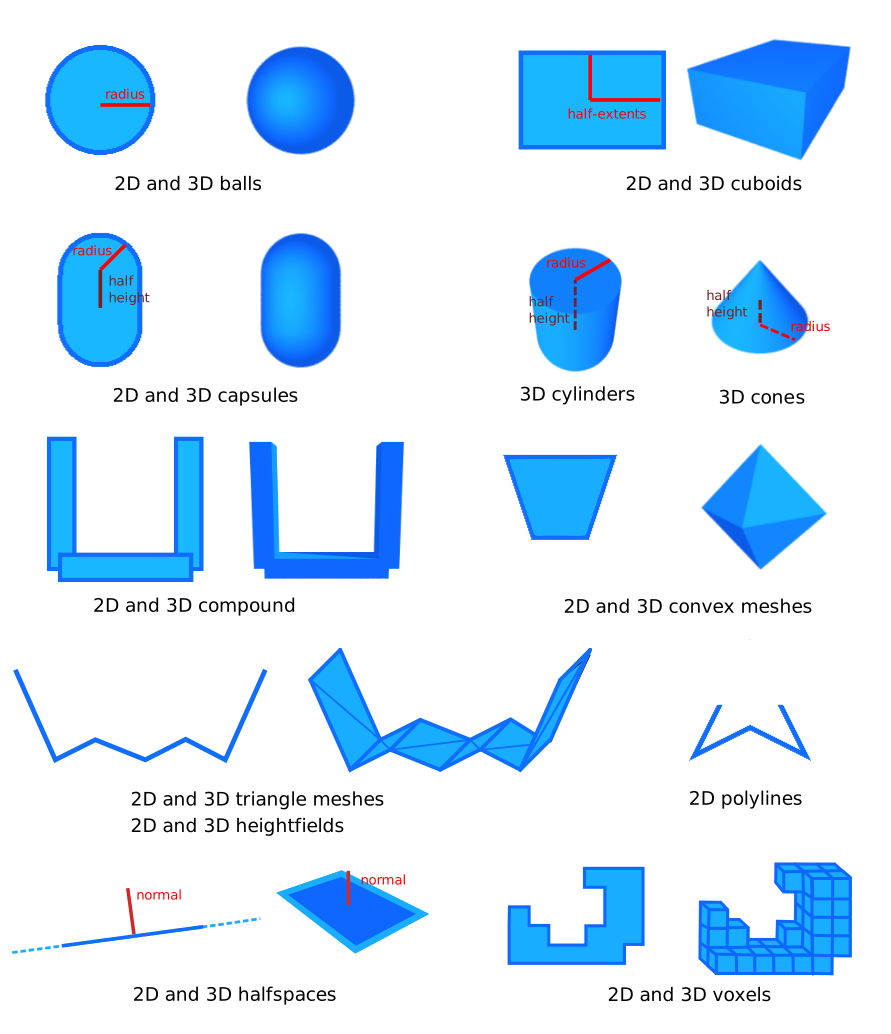
Shapes only hold information about their geometry. Their world-space position is given by the collider's position. Balls, cuboids, capsules, cylinders, and cones are all described by their half-height and/or radius. Compound shapes, convex meshes, triangle meshes, heightfields, and polylines are more complicated shapes described in the next paragraphs.
Convex meshes
A convex mesh is a shape such that, if two points are part of the shape, then the segment between these two points is also part of the shape:
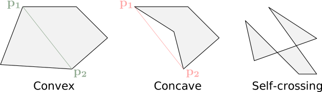
There are two ways of creating a collider with a convex shape:
-
Using
r3ShapeDesc_SetConvexHull(&desc.shape, points)(orr3ConvexHullSharedShape(points)). This is the simplest approach: it will automatically compute the convex hull of the given set of points. A convex hull is the smallest convex shape that contains all the given points. -
Using
r3ConvexMeshSharedShape(points, indices)in 3D orr2ConvexPolylineSharedShape(points)in 2D. This takes a mesh described by its vertex buffer and index buffer and assumes it is already convex (you need to ensure that it is convex yourself). This will be more efficient than ther3ShapeDesc_SetConvexHullconstructor because it won't perform any calculations to ensure convexity. However, if the input mesh isn't actually convex, the collision-detection for that shape will give an incorrect result.
Triangle meshes and polylines
Triangle meshes (in 3D) and polylines (in 2D) can be used to describe the boundary of any kind of shape. This is generally useful to describe the fixed environment in games (terrains, buildings, etc.) Triangle meshes and polylines are defined by their vertex buffer and their index buffer. The winding of the triangles of a triangle mesh does not matter. Its topology doesn't matter either (it can have holes, cavities, doesn't need to be closed or manifold). It is however strongly recommended to avoid triangles that are long and thin because they can result in a lower numerical stability of collision-detection.
A triangle mesh/polyline is composed of triangles/segments with no thickness. This means that geometric queries like point-containment tests won't work intuitively because the triangle mesh is assumed to have no interior.
Triangle mesh
A triangle-mesh collider can be built
with r3ShapeDesc_SetTrimesh(&desc.shape, vertices, indices, flags) (or r3TrimeshSharedShape(vertices, indices)) where
vertices is the buffer containing all the vertices of the mesh, and indices is a set of indices indicating what vertex is used by
what triangle. The vertex buffer and index buffer may have different lengths, and any vertex can be shared
by multiple triangles.
To have more control over the resulting Trimesh,
you can give a combination of the R3_TRIMESH_* flags to the last argument of r3ShapeDesc_SetTrimesh (or call r3TrimeshSharedShapeWithFlags(vertices, indices, flags)).
For example, R3_TRIMESH_FIX_INTERNAL_EDGES is a popular choice to help with correcting ghost collision.
See the documentation of the R3_TRIMESH_* constants in rapier.h for more information.
Polyline
A polyline collider can be built
with r3ShapeDesc_SetPolyline(&desc.shape, vertices, indices, flags) (or r3PolylineSharedShape(vertices, indices)) where
vertices is the buffer containing all the vertices of the polyline, and indices is an optional set of indices
indicating what vertex is used by what segment. The vertex buffer and index buffer may have different lengths, and any
vertex can be shared by multiple segments. If the given index buffer is empty then the input vertices are assumed to
form a line strip, i.e., the polyline is formed from the segments [vertices[0], vertices[1]], [vertices[1], vertices[2]], etc.
A triangle-mesh and a polyline are two-sided by default: they generate contacts on both of their sides, which lets a
body crushed against a thin wall squeeze through it when the contact normal flips. This is why they can also be built
as oriented (one-sided) shapes, with the R2_POLYLINE_ORIENTED flag of r2ShapeDesc_SetPolyline (or with
r2OrientedPolylineSharedShape) in 2D, and with the R3_TRIMESH_ORIENTED flag of r3ShapeDesc_SetTrimesh (or of
r3TrimeshSharedShapeWithFlags) in 3D. An oriented shape only collides on its outward side, which is given by the
winding of its vertices, and is therefore the right choice for the walls of a container.
It is discouraged to use a triangle meshes or a polylines for colliders attached to dynamic rigid-bodies. Because they have no interior, it is easy for another object to get stuck into them. In order to simulate properly non-convex objects, it is recommended to use a convex decomposition with a compound shape instead.
Heightfields

Heightfields are a more restrictive version of triangle-meshes and polylines. However, they can be easier to define and use much less memory. Therefore heightfields are useful to define large parts of terrains with simple topologies.
A 3D heightfield is basically large rectangle in the X-Z plane, subdivided in a grid pattern at regular intervals. Each
vertex of this subdivision is given a height, i.e., the coordinate of that point along the Y axis. A 3D heightfield
collider can be created
with r3HeightfieldSharedShape(heights, rows, columns, scale) (or the R3_SHAPE_DESC_HEIGHTFIELD shape kind) where
heights is a matrix indicating the altitude of each subdivision point of that heightfield (given as a flat array of rows * columns heights in column-major order). The number of rows of that
matrix is the number of subdivision along the Z axis, and the number of columns is the number of subdivision along the
X axis. The scale argument indicates the size of the rectangle of the X-Z plane.
A heightfield collider can be given any orientation by changing the orientation of the collider itself.
A 2D heightfield is a large segment along the X axis, subdivided at regular intervals. Each vertex of this
subdivision is given a height, i.e., the coordinate of that point along the Y axis. A 2D heightfield collider
can be created
with r2HeightfieldSharedShape(heights, rows, 1, scale) (or the R2_SHAPE_DESC_HEIGHTFIELD shape kind with a single column) where
heights is a vector indicating the altitude of each subdivision point of that heightfield. The number of elements on
that vector is the number of subdivision of the heightfield. The scale argument indicates the length of the subdivided
segment along the X axis.
Voxels
Voxel shapes are useful to represent 3D volumes made of small uniform cubes (voxels), such as Minecraft-like worlds or volumetric data. Unlike triangle meshes, voxel-based shapes can offer improved collision detection robustness and performance due to their regular structure.
A voxel shape is a shared shape constructed from a grid of occupied cells, e.g., with
r3VoxelsSharedShapeFromPoints which fills the cells containing the given points:
- Example 2D
- Example 3D
// A voxels shape from arbitrary points.
R2Vector points[] = {{0.0, 0.0}, {1.0, 1.0}, {-1.0, 1.0}};
R2SharedShape *shape = r2VoxelsSharedShapeFromPoints(r2Vector(1.0, 1.0), (R2VectorView){points, 3});
R2ColliderDesc collider = r2DefaultColliderDesc();
collider.shape.kind = R2_SHAPE_DESC_SHARED;
collider.shape.sharedShape = shape;
// A voxels shape from arbitrary points.
R3Vector points[] = {{0.0, 0.0, 0.0}, {1.0, 1.0, 1.0}};
R3SharedShape *shape = r3VoxelsSharedShapeFromPoints(r3Vector(1.0, 1.0, 1.0), (R3VectorView){points, 2});
R3ColliderDesc collider = r3DefaultColliderDesc();
collider.shape.kind = R3_SHAPE_DESC_SHARED;
collider.shape.sharedShape = shape;
You can also voxelize a mesh (a polyline in 2D, or a triangle mesh in 3D) with r3VoxelizedMeshSharedShape:
R2SharedShape *shape =
    r2VoxelizedMeshSharedShape((R2VectorView){mesh, 2}, (R2SurfaceElementView){indices, 2}, 0.2);
The voxels of a collider with a voxel shape can then be inspected with r3Collider_IsVoxels and
r3Collider_VoxelAtFlatId, and filled or cleared individually with r3Collider_SetVoxel.
Compound shapes
It is not recommended to use a triangle mesh or polyline for the shape of a collider attached to a dynamic rigid-body. The alternative is to use a compound shape to model a non-convex object as the union of multiple convex parts (which can be cuboids, balls, convex meshes, etc.) This is commonly known as a convex decomposition.
An alternative to using a compound shape is to attach multiple colliders to the same rigid-body: all the colliders will move with the rigid-body automatically, and the simulation quality (contact resolution, stability) is identical with both approaches. They differ in other ways, so pick based on how you use the object:
- Performance: a compound shape is a single collider, so the broad-phase handles one entry (with its own internal acceleration structure for the parts) instead of one entry per collider. With many parts (hundreds or more), a compound shape makes the physics step significantly cheaper, especially while the rigid-body is awake.
- Collision events: each collider generates its own individual collision start/stop events and can have its own friction, restitution, collision groups, or sensor status. A compound shape is a single collider: one set of events and properties for the whole shape.
- Mutability: adding or removing one collider from a rigid-body is easy and cheap, whereas adding or removing a part of a compound shape requires rebuilding the whole compound shape.
To build a compound shape, it is possible to directly provide the set of shapes as well as their position in the
compound shape's local space, as an array of R3CompoundShapeDesc given to a shape description with the
R3_SHAPE_DESC_COMPOUND kind (or to r3CompoundSharedShape):
R2CompoundShapeDesc parts[] = {{pos1, shape}, {pos2, shape}};
R2ColliderDesc collider = r2DefaultColliderDesc();
collider.shape.kind = R2_SHAPE_DESC_COMPOUND;
collider.shape.children = (R2CompoundShapeView){parts, 2};
It is also possible to build a compound shape modelling the convex decomposition of a 3D triangle mesh or 2D polyline
using the r3ConvexDecompositionSharedShape(vertices, indices) function. This will automatically create a compound
shape composed of multiple convex meshes obtained from the approximate convex decomposition of the triangle mesh (or
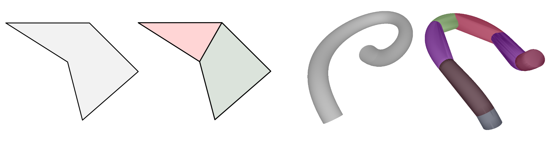
polyline in 2D) using the VHACD algorithm. Here are examples of a 2D concave
polygon decomposed into two convex parts as well as a 3D mesh with its approximate convex decomposition composed of 7
convex parts:
Round shapes
Some shapes have round variants: RoundCuboid, RoundCylinder, RoundCone, RoundConvexPolygon and
RoundConvexPolyhedron. These are shapes to which is added a small thickness with round border:
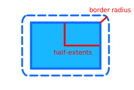
For algorithmic reasons, collision-detection involving round cylinders, round cones, round convex polygon or round convex polyhedron will be faster than collision-detection with their non-round counterparts. However, collision-detection with round-cuboids will be slower than collision-detection with regular cuboids.
Colliders with round shapes are built in a way very similar to their non-round
counterparts, e.g., r3RoundCuboidColliderDesc.
These constructors take one additional parameter: the size of the added thickness called border_radius.
The round shapes are created with the following functions:
r3RoundCuboidColliderDesc(half_extents, border_radius)for a round cuboid.r3RoundCylinderColliderDesc(half_height, radius, border_radius)for a round cylinder (3D only).r3RoundConeColliderDesc(half_height, radius, border_radius)for a round cone (3D only).r3RoundConvexHullSharedShape(points, border_radius)for the round convex hull of a set of points: a round convex polygon in 2D, or a round convex polyhedron in 3D.
The first three also have a shared shape version, e.g., r3RoundCuboidSharedShape.
Mass properties
The mass properties of a rigid-body is computed as the sum of the mass-properties manually set by the user for the rigid-body, plus the mass-properties of the colliders attached to it. There are two ways to define the mass-properties of a collider:
- The easiest, automatic, way: by giving the collider a non-zero density (the default density is 1.0) or a non-zero mass. This will make sure the other mass-properties like the angular inertia tensor are computed automatically from the collider's shape.
- The manual way: by giving an explicit mass and angular inertia to the collider.
It is recommended to use the density-based or mass-based approaches as it will ensure the automatically-computed mass-properties are coherent with the geometric shape. Wrong mass-properties (especially the angular inertia part and center-of-mass location) may lead to odd behaviors. The manual approach is usually useful when modeling real-world objects for which you already know the real-world mass, center-of-mass, and angular inertia tensor.
The mass-properties of a collider can be set when the collider is created, by setting the massMode of its description to R3_MASS_DENSITY (the default), R3_MASS_TOTAL, or R3_MASS_PROPERTIES, and the corresponding density, mass, or massProperties field:
- Example 2D
- Example 3D
R2RigidBodyDesc rigid_body = r2DynamicRigidBodyDesc();
R2RigidBodyHandle rigid_body_handle = r2InsertRigidBody(world, &rigid_body);
// First option: by setting the density of the collider (or we could just leave
//               its default value 1.0).
R2ColliderDesc collider = r2CuboidColliderDesc(r2Vector(1.0, 2.0));
collider.density = 2.0;
// Second option: by setting the mass of the collider.
collider = r2CuboidColliderDesc(r2Vector(1.0, 2.0));
collider.massMode = R2_MASS_TOTAL;
collider.mass = 0.8;
// Third option: by setting the mass-properties explicitly.
collider = r2CuboidColliderDesc(r2Vector(1.0, 2.0));
collider.massMode = R2_MASS_PROPERTIES;
collider.massProperties = (R2MassProperties){
    .local_com = r2Vector(0.0, 1.0),
    .mass = 0.5,
    .principal_inertia = 0.3,
};
// When the collider is attached, the rigid-body's mass and angular
// inertia is automatically updated to take the collider into account.
r2InsertCollider(rigid_body_handle, &collider);
R3RigidBodyDesc rigid_body = r3DynamicRigidBodyDesc();
R3RigidBodyHandle rigid_body_handle = r3InsertRigidBody(world, &rigid_body);
// First option: by setting the density of the collider (or we could just leave
//               its default value 1.0).
R3ColliderDesc collider = r3CuboidColliderDesc(r3Vector(1.0, 2.0, 3.0));
collider.density = 2.0;
// Second option: by setting the mass of the collider.
collider = r3CuboidColliderDesc(r3Vector(1.0, 2.0, 3.0));
collider.massMode = R3_MASS_TOTAL;
collider.mass = 0.8;
// Third option: by setting the mass-properties explicitly.
collider = r3CuboidColliderDesc(r3Vector(1.0, 2.0, 3.0));
collider.massMode = R3_MASS_PROPERTIES;
collider.massProperties = (R3MassProperties){
    .local_com = r3Vector(0.0, 1.0, 0.0),
    .mass = 0.5,
    .principal_inertia = r3Vector(0.3, 0.2, 0.1),
    // The identity rotation: the principal inertia axes are the local axes.
    .principal_inertia_local_frame = {0.0, 0.0, 0.0, 1.0},
};
// When the collider is attached, the rigid-body's mass and angular
// inertia is automatically updated to take the collider into account.
R3ColliderHandle collider_handle = r3InsertCollider(rigid_body_handle, &collider);
The explicit mass-properties are given by a R3MassProperties: the center-of-mass local_com in the collider's local
space, the mass, and the principal_inertia (a scalar in 2D, or the three principal angular inertia in 3D, along
the axes given by the principal_inertia_local_frame rotation).
They can also be modified after the creation of the collider with r3Collider_SetDensity, r3Collider_SetMass, or
r3Collider_SetMassProperties. Each of these functions (as well as the massMode of the description) replaces the
mass-properties previously set by any of the others: for example, calling r3Collider_SetMass on a collider created
with a density makes its density be ignored. The mass-properties of the rigid-body the collider is attached to are
then updated automatically at the next simulation step (or immediately with
r3RigidBody_RecomputeMassPropertiesFromColliders). The resulting volume, density, mass, and local mass-properties of
a collider can be read with r3Collider_Volume, r3Collider_Density, r3Collider_Mass, and
r3Collider_MassProperties.
Position
The position of a collider represents its location (translation) in 2D or 3D world-space as well as its orientation (rotation).
Its translational part is represented as a vector (R3Vector) and its rotational part (R3Rotation) as an unit quaternion (in 3D) or an angle (in 2D). Both are combined into a pose (the R3Pose type).
Please read carefully the paragraph after the next example. It explains how the collider position (and the action of setting this position) behaves differently when it is attached to a rigid-body.
It is possible to set this position when the collider is created or after its creation:
- Example 2D
- Example 3D
/* Set the collider position when the collider is created. */
R2ColliderDesc collider = r2BallColliderDesc(0.5);
collider.position.translation = r2Vector(1.0, 2.0);
collider.position.rotation = r2Rotation(0.4);
// Set both translation and rotation at once.
collider.position = r2Pose(r2Vector(1.0, 2.0), r2Rotation(0.4));
/* Set the collider position after the collider creation. */
r2Collider_SetTranslation(collider_handle, r2Vector(1.0, 2.0));
r2Collider_SetRotation(collider_handle, r2Rotation(0.4));
// Set both the translation and rotation at once.
r2Collider_SetPosition(collider_handle, r2Pose(r2Vector(1.0, 2.0), r2Rotation(0.4)));
R2Vector translation = r2Collider_Translation(collider_handle);
assert(translation.x == 1.0 && translation.y == 2.0);
assert(fabs(r2Collider_Rotation(collider_handle).angle - 0.4) < 1.0e-6);
/* Set the collider position when the collider is created. */
R3ColliderDesc collider = r3BallColliderDesc(0.5);
collider.position.translation = r3Vector(1.0, 2.0, 3.0);
collider.position.rotation = r3RotationFromAxisAngle(r3Vector(0.0, 0.0, 1.0), 0.4);
// Set both translation and rotation at once.
collider.position =
    r3Pose(r3Vector(1.0, 2.0, 3.0), r3RotationFromAxisAngle(r3Vector(0.0, 0.0, 1.0), 0.4));
/* Set the collider position after the collider creation. */
R3Rotation rotation = r3RotationFromAxisAngle(r3Vector(0.0, 0.0, 1.0), 0.4);
r3Collider_SetTranslation(collider_handle, r3Vector(1.0, 2.0, 3.0));
r3Collider_SetRotation(collider_handle, rotation);
// Set both the translation and rotation at once.
r3Collider_SetPosition(collider_handle, r3Pose(r3Vector(1.0, 2.0, 3.0), rotation));
R3Vector translation = r3Collider_Translation(collider_handle);
assert(translation.x == 1.0 && translation.y == 2.0 && translation.z == 3.0);
If a collider is attached to a rigid-body, its position is automatically updated by the physics pipeline when a rigid-body is moved by the physics pipeline. If a change to the rigid-body position is made by the user then the collider position will be updated during the next timestep.
Therefore, directly setting the position of a collider attached to a rigid-body (with r3Collider_SetPosition, r3Collider_SetTranslation, or r3Collider_SetRotation) will have no lasting effect. Instead, it is possible to set the position of the collider relative to the rigid-body it is attached to: this is the position field of its description, which can be modified after its creation with r3Collider_SetPositionWrtParent:
- Example 2D
- Example 3D
R2RigidBodyDesc rigid_body = r2DynamicRigidBodyDesc();
R2RigidBodyHandle rigid_body_handle = r2InsertRigidBody(world, &rigid_body);
R2ColliderDesc collider = r2BallColliderDesc(0.5);
collider.position.translation = r2Vector(1.0, 2.0);
// Attach the collider to the rigid-body. The description's position is
// the collider's position wrt. the rigid-body.
R2ColliderHandle collider_handle = r2InsertCollider(rigid_body_handle, &collider);
/* Set the collider position wrt. its parent after the collider creation. */
r2Collider_SetPositionWrtParent(collider_handle, r2TranslationPose(r2Vector(1.0, 2.0)));
R2Vector translation = r2Collider_PositionWrtParent(collider_handle).translation;
assert(translation.x == 1.0 && translation.y == 2.0);
R3RigidBodyDesc rigid_body = r3DynamicRigidBodyDesc();
R3RigidBodyHandle rigid_body_handle = r3InsertRigidBody(world, &rigid_body);
R3ColliderDesc collider = r3BallColliderDesc(0.5);
collider.position.translation = r3Vector(1.0, 2.0, 3.0);
// Attach the collider to the rigid-body. The description's position is
// the collider's position wrt. the rigid-body.
R3ColliderHandle collider_handle = r3InsertCollider(rigid_body_handle, &collider);
/* Set the collider position wrt. its parent after the collider creation. */
r3Collider_SetPositionWrtParent(collider_handle, r3TranslationPose(r3Vector(1.0, 2.0, 3.0)));
R3Vector translation = r3Collider_PositionWrtParent(collider_handle).translation;
assert(translation.x == 1.0 && translation.y == 2.0 && translation.z == 3.0);
Friction
Friction is a force that opposes the relative tangential motion between two rigid-bodies with colliders in contact. This force has a direction orthogonal to the contact normal and opposite to the relative rigid-body motion at the contact point. Following the Coulomb friction model, the maximum magnitude of this force is the magnitude of the force along the contact normal multiplied by a friction coefficient. A friction coefficient of 0 implies no friction at all (completely sliding contact) and a coefficient greater or equal to 1 implies a very strong friction. Values greater than 1 are allowed.
Rapier does not make any distinction between the fixed and dynamic friction coefficients currently.
Each collider has its own friction coefficient. This means that when two colliders are in contact, we need to apply a
rule that combines the friction coefficients of these two colliders into a single coefficient that will be used for
the contact. This rule is described by the R3_COMBINE_* constants:
-
R3_COMBINE_AVERAGE: the average of the two coefficients is used for the contact. -
R3_COMBINE_MIN: the minimum among the two coefficients is used for the contact. -
R3_COMBINE_MULTIPLY: the product of the two coefficients is used for the contact. -
R3_COMBINE_MAX: the maximum among the two coefficients is used for the contact. -
R3_COMBINE_CLAMPED_SUM: the sum of the two coefficients, clamped to , is used for the contact. -
R3_COMBINE_GEOMETRIC_MEAN: the square root of the product of the two coefficients is used for the contact. It is stricter than the average (any coefficient of zero results in zero) but less aggressive than the product.
By default, the R3_COMBINE_AVERAGE rule is used. Each collider can be given its own friction combine rule. When two colliders are in
contact, we need to select one of their combine rule. The following precedence is used:
R3_COMBINE_GEOMETRIC_MEAN > R3_COMBINE_CLAMPED_SUM > R3_COMBINE_MAX > R3_COMBINE_MULTIPLY > R3_COMBINE_MIN > R3_COMBINE_AVERAGE, i.e., the rule with the greatest value wins.
For example if one collider with the Multiply friction combine rule is in contact with a collider with the Average friction
combine rule, then the Multiply rule will be applied for the friction coefficient of this contact (i.e. the coefficients
of both colliders will be multiplied to obtain the coefficient used by the contact).
The combine rule system exists to cover a wide variety of use-cases efficiently. If this is not flexible enough, it is possible to get full control over the selection of friction coefficients for each contact point using contact modification. For example, contact modification allows the simulation of colliders with non-uniform friction coefficients.
The friction coefficient and friction combine rule can both be set when the collider is created or after its creation:
/* Set the friction coefficient and friction combine rule
when the collider is created. */
R2ColliderDesc collider = r2BallColliderDesc(0.5);
collider.friction = 0.7;
collider.frictionCombineRule = R2_COMBINE_MIN;
/* Set the friction coefficient and friction combine rule
after the collider creation. */
r2Collider_SetFriction(collider_handle, 0.7);
r2Collider_SetFrictionCombineRule(collider_handle, R2_COMBINE_MIN);
assert(r2Collider_Friction(collider_handle) == (R2Real)0.7);
assert(r2Collider_FrictionCombineRule(collider_handle) == R2_COMBINE_MIN);
Restitution
Restitution controls how elastic (aka. bouncy) a contact is. The elasticity of a contact is controlled by the restitution coefficient. A restitution coefficient set to 1 (fully elastic contact) implies that the exit velocity at a contact has the same magnitude as the entry velocity along the contact normal: it is as if you drop a bouncing ball and it gets back to the same height after the bounce. A restitution coefficient set to 0 implies that the exit velocity at a contact will be zero along the contact normal: it's as if you drop a ball but it doesn't bounce at all.
The friction and restitution coefficients are both managed in very similar ways: with the combine rules or with contact modification. The paragraph below is almost identical to the paragraph about friction.
Each collider has its own restitution coefficient. This means that when two colliders are in contact, we need to apply a
rule that combines the restitution coefficients of these two colliders into a single coefficient that will be used for
the contact. This rule is described by the R3_COMBINE_* constants:
-
R3_COMBINE_AVERAGE: the average of the two coefficients is used for the contact. -
R3_COMBINE_MIN: the minimum among the two coefficients is used for the contact. -
R3_COMBINE_MULTIPLY: the product of the two coefficients is used for the contact. -
R3_COMBINE_MAX: the maximum among the two coefficients is used for the contact. -
R3_COMBINE_CLAMPED_SUM: the sum of the two coefficients, clamped to , is used for the contact. -
R3_COMBINE_GEOMETRIC_MEAN: the square root of the product of the two coefficients is used for the contact. It is stricter than the average (a coefficient of zero results in zero) but less aggressive than the product.
By default, the R3_COMBINE_AVERAGE rule is used. Each collider can be given its own restitution combine rule. When two colliders are in
contact, we need to select one of their combine rule. The following precedence is used:
R3_COMBINE_GEOMETRIC_MEAN > R3_COMBINE_CLAMPED_SUM > R3_COMBINE_MAX > R3_COMBINE_MULTIPLY > R3_COMBINE_MIN > R3_COMBINE_AVERAGE, i.e., the rule with the greatest value wins.
For example if one collider with the Multiply restitution combine rule is in contact with a collider with the Average restitution
combine rule, then the Multiply rule will be applied for the restitution coefficient of this contact (i.e. the coefficients
of both colliders will be multiplied to obtain the coefficient used by the contact).
The combine rule system exists to cover a wide variety of use-cases efficiently. If this is not flexible enough, it is possible to get full control over the selection of restitution coefficients for each contact point using contact modification. For example, contact modification allows the simulation of colliders with non-uniform restitution coefficients.
The restitution coefficient and restitution combine rule can both be set when the collider is created or after its creation:
/* Set the restitution coefficient and restitution combine rule
when the collider is created. */
R2ColliderDesc collider = r2BallColliderDesc(0.5);
collider.restitution = 0.7;
collider.restitutionCombineRule = R2_COMBINE_MIN;
/* Set the restitution coefficient and restitution combine rule
after the collider creation. */
r2Collider_SetRestitution(collider_handle, 0.7);
r2Collider_SetRestitutionCombineRule(collider_handle, R2_COMBINE_MIN);
assert(r2Collider_Restitution(collider_handle) == (R2Real)0.7);
assert(r2Collider_RestitutionCombineRule(collider_handle) == R2_COMBINE_MIN);
Contact skin
The contact skin of a collider acts as if the collider was enlarged by a skin of the given thickness: the objects touching it are kept that much further apart. The default is zero, i.e., no skin at all.
A non-zero contact skin can improve the performances and, in some cases, the stability of the simulation, because the contacts will have more room to prevent penetrations. However, as a result it leaves a small gap between the colliding objects, equal to the sum of their skins. Therefore the skin should be small enough for that gap to remain invisible, or to be hidden by the rendering assets. The contact skin is especially relevant when using non-convex shapes made of thin features like triangle meshes and polylines.
/* Set the contact skin when the collider is created. */
R2ColliderDesc collider = r2BallColliderDesc(0.5);
collider.contactSkin = 0.01;
/* Set the contact skin after the collider creation. */
r2Collider_SetContactSkin(collider_handle, 0.01);
assert(r2Collider_ContactSkin(collider_handle) == (R2Real)0.01);
Collision groups and solver groups
The most efficient way of preventing some pairs of colliders from interacting with each other is to use collision groups or solver groups. Each collider is given:
- A
collision_groupsfor filtering what pair of colliders should have their contacts (or intersection test if at least one of the colliders is a sensor) computed by the narrow-phase. This filtering happens right after the broad-phase, at the beginning of the narrow phase. - A
solver_groupsfor filtering what pair of colliders should have their contact forces computed. This filtering happens at the end of the narrow-phase, before the constraints solver.
In other words, the solver_groups is here to prevent contact forces from being computed between some colliders, whereas the
collision_groups will also prevent the contact themselves (and contact events) from being computed. The
collision_groups should be preferred most of the time because it skips more computations. The solver_groups is only
useful if you really want the contact information to be computed but not the forces, for example so that you can apply your
own forces based on these contacts.
A collision group or solver group is described as a pair of bit masks:
- The groups membership indicates what groups the collider is part of (one bit per group).
- The groups filter indicates what groups the collider can interact with (one bit per group).
The collision groups and solver groups (the collisionGroups and solverGroups fields of the collider description)
are given by a R3InteractionGroups structure containing both bit masks, as memberships and filter, as well as a
test_mode explained at the end of this section.
Because the memberships and filter bit masks are uint32_t there is a total of 32 groups. By default all bits
are set to 1: the collider is part of every group, and can interact with every group.
For example, let's say we want our collider A to be part of the groups [0, 2, 3] and to be able to interact
with the groups [2], then its groups membership is 0b1101 = 0xD and its groups filter is 0b0100 = 0x4. The collision groups and solver groups of a collider can be set
during or after its creation:
/* Set the collision groups and solver groups when the collider is created. */
R2ColliderDesc collider = r2BallColliderDesc(0.5);
collider.collisionGroups = (R2InteractionGroups){
    .memberships = (1u << 0) | (1u << 2) | (1u << 3), // Groups 0, 2, and 3.
    .filter = 1u << 2,                                // Group 2.
    .test_mode = R2_GROUPS_AND,
};
collider.solverGroups = (R2InteractionGroups){
    .memberships = (1u << 0) | (1u << 1),             // Groups 0 and 1.
    .filter = (1u << 0) | (1u << 1) | (1u << 3),      // Groups 0, 1, and 3.
    .test_mode = R2_GROUPS_AND,
};
/* Set the collision groups and solver groups after the collider creation. */
R2InteractionGroups collision_groups = {
    .memberships = (1u << 0) | (1u << 2) | (1u << 3), // Groups 0, 2, and 3.
    .filter = 1u << 2,                                // Group 2.
    .test_mode = R2_GROUPS_AND,
};
R2InteractionGroups solver_groups = {
    .memberships = (1u << 0) | (1u << 1),             // Groups 0 and 1.
    .filter = (1u << 0) | (1u << 1) | (1u << 3),      // Groups 0, 1, and 3.
    .test_mode = R2_GROUPS_AND,
};
r2Collider_SetCollisionGroups(collider_handle, collision_groups);
r2Collider_SetSolverGroups(collider_handle, solver_groups);
assert(r2Collider_CollisionGroups(collider_handle).memberships == collision_groups.memberships);
assert(r2Collider_SolverGroups(collider_handle).filter == solver_groups.filter);
After the broad-phase detects that two colliders A and B may start being in contact, the narrow-phase will check the collision
groups of both colliders to see if it needs to compute contacts. The check operates as follows:
- If the collider
Ais not member of any collision group in the filter ofB, then no contact is computed. - If the collider
Bis not member of any collision group in the filter ofA, then no contact is computed. - The exact bit-wise check is the following:
   (r3Collider_CollisionGroups(a).memberships & r3Collider_CollisionGroups(b).filter) != 0
&& (r3Collider_CollisionGroups(b).memberships & r3Collider_CollisionGroups(a).filter) != 0
If this test succeeds, then the narrow-phase will compute the contacts. Then it will check the solver groups of both
colliders, using the same kind of tests as described before but using the solver_groups instead of collision_groups.
If the test succeeds then the constraints solver will compute forces for these contacts. Otherwise, it won't.
This is the behavior of the default R3_GROUPS_AND test mode (the test_mode field of R3InteractionGroups). If
both colliders use the R3_GROUPS_OR test mode, then satisfying only one of these two conditions is enough for the
contacts (or forces) to be computed.
Active collision types
By default, collision-detection is completely disabled between two colliders when both are attached to non-dynamic bodies.
Sometimes, it can be useful to enable collision-detection between, e.g., a collider attached to a kinematic rigid-body
and a collider attached to a fixed rigid-body. This can be done by modifying the collider's active collision types, a bit mask made of the R3_COLLISION_TYPES_* flags:
/* Set the active collision types when the collider is created. */
R2ColliderDesc collider = r2BallColliderDesc(0.5);
collider.activeCollisionTypes = R2_COLLISION_TYPES_DEFAULT | R2_COLLISION_TYPES_KINEMATIC_FIXED;
/* Set the active collision types after the collider creation. */
r2Collider_SetActiveCollisionTypes(collider_handle,
                                   R2_COLLISION_TYPES_DEFAULT | R2_COLLISION_TYPES_KINEMATIC_FIXED);
assert(r2Collider_ActiveCollisionTypes(collider_handle) & R2_COLLISION_TYPES_DYNAMIC_KINEMATIC);
assert(r2Collider_ActiveCollisionTypes(collider_handle) & R2_COLLISION_TYPES_KINEMATIC_FIXED);
To enable collision-detection between kinematic bodies and fixed bodies (as well as dynamic bodies), set its active collision types to:
R3_COLLISION_TYPES_DEFAULT | R3_COLLISION_TYPES_KINEMATIC_FIXED
Active events
Event handlers are user-defined callbacks used to be
notified when two colliders start/stop touching. By default no collision event is generated by
the narrow-phase. In order to enable a collision event for a pair of colliders, at
least one of the involved colliders must have the corresponding event set as active. An event is activated for a collider
by setting its corresponding active events bit to 1:
- Setting the
R3_COLLISION_EVENTSbit to 1 enables the collision events involving the collider.
The active events of a collider can be set when the collider is created or after its creation:
/* Set the active events when the collider is created. */
R2ColliderDesc collider = r2BallColliderDesc(0.5);
collider.activeEvents = R2_COLLISION_EVENTS;
/* Set the active events after the collider creation. */
r2Collider_SetActiveEvents(collider_handle, R2_COLLISION_EVENTS);
assert(r2Collider_ActiveEvents(collider_handle) & R2_COLLISION_EVENTS);
Active hooks
Physics hooks are user-defined callbacks used to filter-out some contact
pairs, or modify contacts, based on arbitrary user code. In order to enable a physics hook for a pair of colliders, at
least one of the involved colliders must have the corresponding hook set as active. A hook is activated for a collider
by setting its corresponding active hooks bit to 1:
-
Setting the
R3_FILTER_CONTACT_PAIRSbit to 1 enables the manual filtering of all the contact pairs involving the collider. -
Setting the
R3_FILTER_INTERSECTION_PAIRbit to 1 enables the manual filtering of all the intersection pairs involving the collider. -
Setting the
R3_MODIFY_SOLVER_CONTACTSbit to 1 enables the manual contact modification for all the contact manifolds involving the collider.
The active hooks of a collider can be set when the collider is created or after its creation (the callbacks themselves are given to r3Step as a R3PhysicsHooks, see physics hooks):
/* Set the active hooks when the collider is created. */
R2ColliderDesc collider = r2BallColliderDesc(0.5);
collider.activeHooks = R2_FILTER_CONTACT_PAIRS | R2_MODIFY_SOLVER_CONTACTS;
/* Set the active hooks after the collider creation. */
r2Collider_SetActiveHooks(collider_handle, R2_FILTER_CONTACT_PAIRS | R2_MODIFY_SOLVER_CONTACTS);
assert(r2Collider_ActiveHooks(collider_handle) & R2_FILTER_CONTACT_PAIRS);
assert(r2Collider_ActiveHooks(collider_handle) & R2_MODIFY_SOLVER_CONTACTS);
User-data
Each collider can be given a user-defined data of type R3UserData: a 128-bits integer split into its low and
high 64-bits halves. This integer can have any value and is never used/modified by the physics-engine. This can for
example be useful to store the index (or the address) of the game object the collider belongs to, or to add some
custom data for personalized contact filtering/modification. Keep in mind that
Rapier doesn't own anything encoded in the user-data: if it stores a pointer, the pointed data must be managed by your
application.
This user-data can be set when the collider is created or after its creation:
/* Set the user-data when the collider is created. */
R2ColliderDesc collider = r2BallColliderDesc(0.5);
collider.userData = (R2UserData){.low = 42, .high = 0};
/* Set the user-data after the collider creation. */
r2Collider_SetUserData(collider_handle, (R2UserData){.low = 42, .high = 0});
assert(r2Collider_UserData(collider_handle).low == 42);